PAL 
PAL (Phase Alternation by Line) was developed to fix NTSC (National Television System Committee) problems with color.
Each PAL frame consist of 625 lines, 25 frames per second. All image data is in scan-lines.
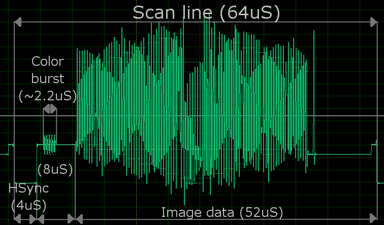
Pic 1. Normal scanline. |
There is 625 scanlines. Not all of them are visible - some are used by vertical retrace and teletext. More information
about it you can find here. Scanlines
during vertical retrace are different than normal ones, the 0V pulses arrives twice as fast as in normal scanlines.
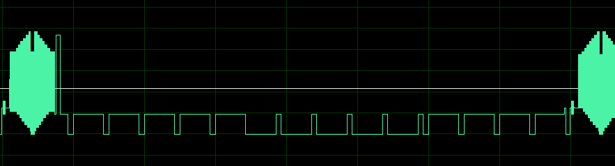
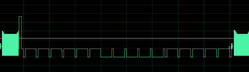
Pic 2. Vertical retraces. |
The color generation is described in next section.
PAL standard defines also how sound should be transmitted, but composite-video contains no audio signal. We are transmitting
Video signal, but we can also try to transmit teletext information.
The Color
Color in PAL is coded using YUV colorspace model, where Y stands for luminance (brightness), and
U V stands for chrominance. This is not the usual way that we used to represent color information
(like RGB or CMYK models). The fact that we are using this method is mainly because the inventors of PAL
had to made it compatible with older black&white television systems.
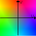
Pic 3. YUV colorspace. | |
[ Y ] [ 0.299 0.587 0.114 ] [ R ]
[ U ] = [-0.147 -0.289 0.436 ]*[ G ]
[ V ] [ 0.615 -0.515 -0.100 ] [ B ]
[ R ] [ 1 0 1.14 ] [ Y ]
[ G ] = [ 1 -0.394 -0.581 ]*[ U ]
[ B ] [ 1 2.028 0 ] [ V ]
Pic 4. RGB to YUV conversions.
|
PAL is using quadrature modulation with phase shift for color. The Y phase is changing every line by 180 deg.
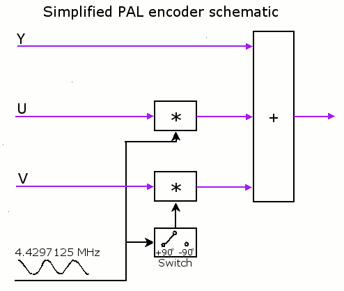
Pic 5. PAL Encoder. |
{ S(t) = Y + U cos (wt) + V sin (wt) for even lines
{ S(t) = Y + U cos (wt) - V sin (wt) for odd lines
{ w=2*pi*f, f= 4.4297125 MHz
In fact, there is no possibility for video-decoder to discover the phase of signal. This information is sent
every line during color-burst phase, when transmitter sends the sinus signal with correct phase. That allows
receiver to synchronise phase every line.
Mathematics
Most projects with microcontroler PAL generation are based on equation:
a sin(x) + b cos(x) = A sin (x + B),
A= sqrt( a^2 + b^2 ), tg(B) = a/b
| Simply: |
why we have to calculate sinus and cosinus functions for each sample when we can only calculate one sinus with phase shift? |
I decided to go some other way. Since my microcontroler is running four times as fast as the color signal, I simply write four
equations for each sample of signal:
S0 = Y + U cos(2pi*0/4) +/- V sin (2pi*0/4)
S1 = Y + U cos(2pi*1/4) +/- V sin (2pi*1/4)
S2 = Y + U cos(2pi*2/4) +/- V sin (2pi*2/4)
S3 = Y + U cos(2pi*3/4) +/- V sin (2pi*3/4)
In fact, the values of cos and sin are well known for this angles so we get...
S0 = Y + U
S1 = Y +/- V
S2 = Y - U
S3 = Y -/+ V
...what is very easy to calculate, even real-time.
| Simply: |
why we have to calculate sinus function for each sample when we can only add or subtract values? |
But there is still one problem with this solution - when I generating color signal I don't have time to do anything else. That's bad. We cannot make loops and other things.
So I tried to make color with 2 samples only, but without changing
color-burst. First I tested it in device and it works, so I went
back to paper to find out what am I really doing ... ;)
To solve this problem we have to know that PAL color signal is
same for two horizontal lines - odd and even pair. The decoder
is applying addition operation to them to get the U, and substraction
to get the V. So in fact we at start got 4 samples:
(S00, S01) at first line
(S10, S11) at second line
when we add and subtract them we got pairs:
U: (S00+S10, S01+S11)
V: (S00-S10, S01-S11)
So, basically we are modulating U and V by using 2 samples for each.
In fact, the thing that is important is fact that we can control
the amplitude of them, which is:
U = S01+S11 - (S00+S11)
V = S01-S11 - (S00-S10) = S01+S10 - (S00+S11)
| Simply: |
why we have to modulate 8 samples to get the color for two pixels when we can only use 4 samples and have free time then? |
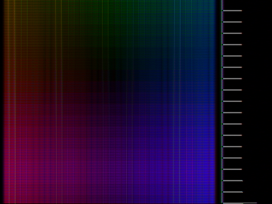
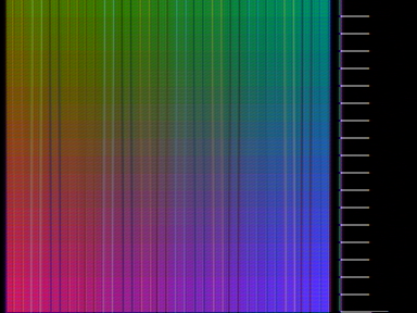
Equations are simplified to illustrate the idea.
Pic 4. Simulation of PAL color coding.
|
|
From TV
2-sample plasma effect on TV
4-sample plasma effect on TV
4-sample plasma effect on TV
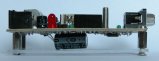
Devboard
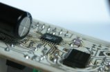
Dev-board
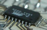
Devboard - ATMEL zoomed
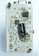
Devboard
Devboard - status LED,
microphone and reset
Devboard - power LED,
programer connector and
joystick connector
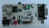
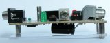
Devboard
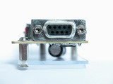
Devboard - RS232 port
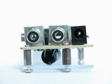
Devboard - video&audio out,
power in
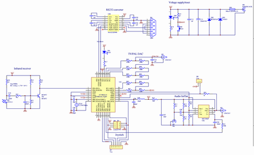
Devboard - schematics,
|
|