Electronic 
I've decided to publish the schematic of my circuit. It contains few mistakes, and during startup few
additional modifications were made:
fixed badly wired MAX232 (let say I was almost sleeping when wiring this);
added resistor to MAX232 power supply;
added bigger capactior for opamp power supply stabilization;
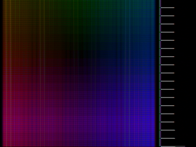
added small capacitor between quartz and mass to stabilize frequency. Even small frequency
errors can make horrible things to color;
changed resistors in audio circuits to provide higher amplify;
Infrared was NOT soldered due to lacks of time, so I don't guarantee it will work;
Joystick part was also NOT soldered...;
Instead of using 7805 I decided to use fuse-based power supply. I have 5V stabilized power supply.
You also have. It's in i.e. PC power supply. I used that one;
(checked if it will survive higher voltages. Under 12V the circuit is still working normally. )
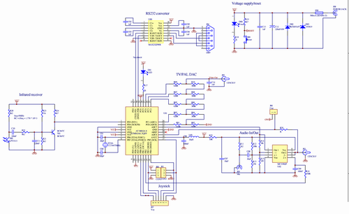
Pic 6. Schematic |
3D Engine
I was thinking for a long time what can I program as an application to the system. We
have small amount of memory (1kB) which forbids for us to use the normal way all graphics
systems works - the video buffer. 8192 pixels? it's 128x64, black&white. My phone got 128x128, so
it's really nothing impressive. "That is NOT the way", I've thinked.
One of the first applications was simple RS232 text terminal. 24x20 monochrome characters, so text buffer
takes almost half of memory. I was happy that I could use program memory to store character
bitmaps, which were 8x8 pixels.
Writing another tetris or pong clone for microcontroler was also not the point I was going to.
Instead, I wanted to do some 3D effects. Then I've realized that it is possible to make simple
wolfenstein 3d - clone. Well, without enemies, textures (goraud shade only), and with screen rotated 90 degrees... but the working one.
It's not finished (and probably will never be) I'm currently publishing only some animated gif with previews.
I may send source code to interested persons.
You have to believe my word that it's working smothly. It's incredible how much we can get from such a small microcontroler...
Currently for download are available source codes for 2 different ways of generating plasma effect.
Problems
Processor speed
When we are generating color signal, we have to change the video output every processor tick. That is very
fast. The processor is giving all the power it have inside just to generate color. And even in this situation
we got limitations...
...
out 0x15, r18
out 0x15, r19
out 0x15, r24
out 0x15, r25
...
We can only send values which we have already in registers. And we can't do anything else than video generation -
we don't have time for loops, register reloads and so on. Unless, of course, we stop generating video signal, or
use 2-sample algorithm instead of 4-sample.
Interrupts
I've used the 16-bit timer/counter running at the processor clock speed. All signals are generated on this
interrupt. But there is problem - in fact we don't know exactly when we get's into interrupt -
it depends of where we were when interrupt comes. Processor have to finish pending instruction, which can
take one, two, three of four processor tacts depending on instruction. Each clock mismatch gives phase
change of 90 deg in signal, which is terrible.
This was fixed by small algorithm on enter to the interrupt procedure - it delay the execution of interrupt
by few clock, depending on what was the delay on start. This can be done by reading the counter of the timer.
...
in r19,0x2C
cpi r19,0x8
breq .skipped_1
brcc .fixed_instruction_lengths
cpi r19,0x6 ;1
brne .fixed_instruction_lengths ;1/2
.skipped_1:
nop
nop
.fixed_instruction_lengths:
...
PAL vertical retrace
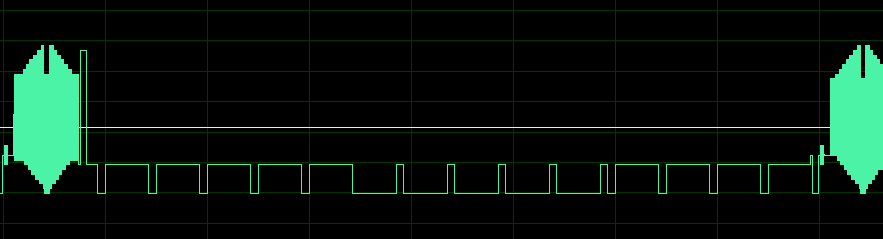
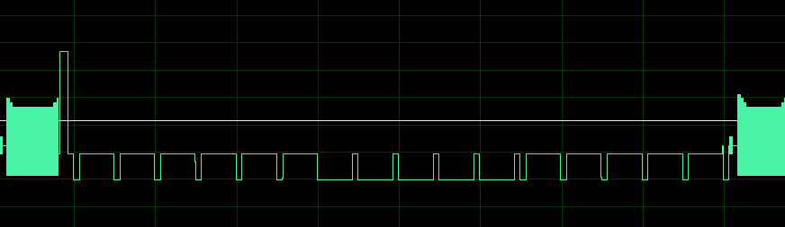
Pic 5. Vertical retraces. |
There were problem with handling of vertical retrace entirelly in interrupt - the signal is changing not only on
the end of scan-line, but also in the middle. So, we can wait in the interrupt till this moment arrives but
this has no sense - we are just wasting processor time. The solution was to change the frequency of the timer
interrrupt to be twice as fast. But even with this some half-scan-lines forces us to wait to the end of scan-line.
Instead, during vertical-retrace the interrupt is changing its frequency more times, and we are not wasting
the procesor power. This code were a little bit ugly to develop.
|
|
From TV

2-sample plasma effect on TV

3D-engine test.
4-sample plasma effect on TV
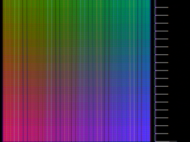
4-sample plasma effect on TV
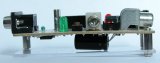
Devboard
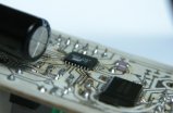
Dev-board
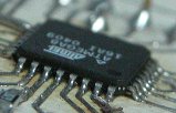
Devboard - ATMEL zoomed
Devboard
Devboard - status LED,
microphone and reset
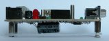
Devboard - power LED,
programer connector and
joystick connector
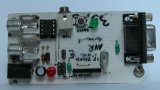
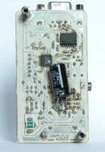
Devboard

Devboard - RS232 port
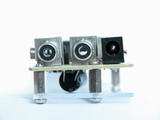
Devboard - video&audio out,
power in
Devboard - schematics,
|
|